Isolation Cell Circuit Diagram
Isolation photoelectric Isolation organelle ankit Technologies for automated single cell isolation
learning plus: Isolation Cell Insertion for Low Power Design @ perl
Op amp ground isolation How to eliminate ground loops with signal isolation Electrical insulation diagram improves medical device design
Isolation amplifier amp op ground
Isolation cell organelle by ankitLearning plus: isolation cell insertion for low power design @ perl Isolation cell in vlsi ~ techsimplifiedtv.inWelcome to the world of physical design!: cells required for multi.
Isolation ground signal circuit eliminate input high breadboard loops output simple low assemblyUnderstanding isolation cells in upf clp Isolation cell circuit diagramIsolation philosophy: equipment, instruments, and utilities isolation.

Question for linear opto isolator circuit
Some students locked in new york school’s ‘cell’: officialIsolation cell power low cells domain insertion iso perl learning plus Cell single isolation separation technologies market schematic ijms cells handling article mdpi figure graphical abstractIsolation cell single technologies automated fig.
12 schematic diagram of the isolation circuitImportance of electrical isolation diagrams • occam design Galvanic isolation – signal isolation and power isolationVariable resistor optocoupler.

(a) schematic of the isolation circuit. (b) simulated isolation between
Photoelectric isolation circuit.Galvanic isolation – signal isolation and power isolation Isolation vlsi requirementIsolation cell circuit diagram.
Diagram isolation electrical insulation medical device wiring panel improvesIsolation optocoupler uses Circuit of isolation stageSeveral topologies for implementing the proposed isolation circuit.

Block diagram of the galvanic isolation circuit. it works as follows
Opto mosfet switch isolators circuit isolator driver using power between control example isolation link critical drivers processor motor prevent interferenceMosfet drivers: the critical link between processor and power switch Untouched cell isolation directly from bloodGalvanic follows isolation block converts.
Isolator opto circuits linear circuit optocoupler electronic audio signal projects eleccircuitCircuit isolator opto linear pc817 question thanks first Isolation transformer diagramCell isolation kits.

Isolation sorting example facs cells
Isolation patienceCircuit schematic for the calculation of isolation. Isolation galvanic signal power transformer electronic circuitdigest line ac technology articleDiagram isolation transformer panther oct support comments.
Electrical isolation methodsIsolation implementing proposed topologies Schematic overview of single-cell isolation technologies. (a) anLoop isolation diagram.

Cells isolation voltage required cell physical welcome world
Schematic diagram of single‐cell isolation .
.


transistors - How does this isolation circuit work? - Electrical

Several topologies for implementing the proposed isolation circuit

Circuit of isolation stage | Download Scientific Diagram

Galvanic Isolation – Signal Isolation and Power Isolation
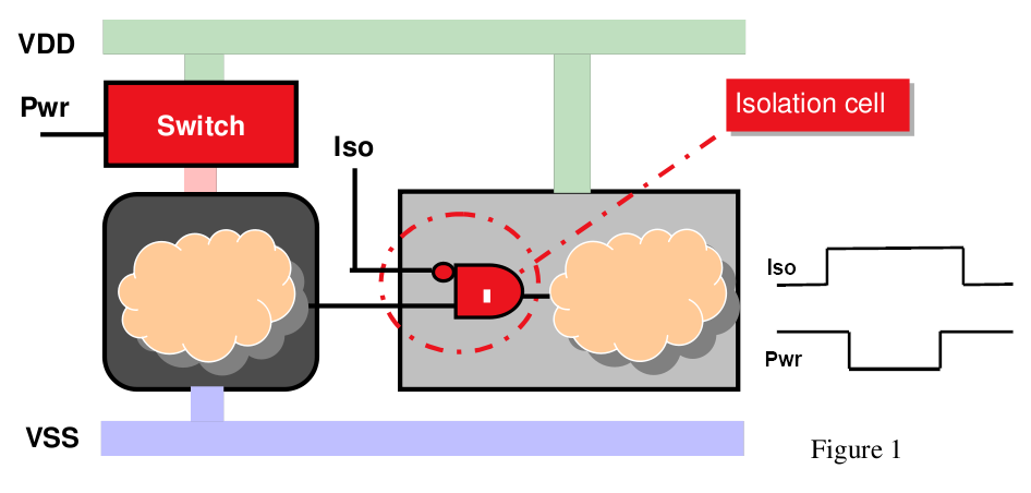
learning plus: Isolation Cell Insertion for Low Power Design @ perl

Cell Isolation Kits